EXL10 Rechargeable Battery Manual
Return to: Horner Tech Support FAQ
This section includes:
Battery Warning -Please refer User Manual, MAN1029, for proper handling of the rechargeable lithium battery.
Lithium Battery Safety - Many of the publicized battery issues are a result of using multiple batteries or flexible battery pack. The OCS uses a small single cell in a metal enclosure, and the battery is UL recognized and comes from quality suppliers. The OCS has safety circuitry built into the charging IC and additional external protection including fusing. These circuits were closely evaluated by UL and Horner engineering for use in hazardous environments.
Overview of Rechargeable Battery Function
The OCS Controllers with rechargeable batteries maintain register data in high-speed RAM when connected to DC power. When DC power is switched off or lost, critical circuits switch over and run on battery power for around 100mS. During this time register and other retentive data is saved to FLASH memory. After this time the real-time clock continues to run on the battery at a very low power level. The battery is designed to maintain the real-time clock for a year or more in the powered-down state. When powered, the OCS controller recharges the battery as necessary. Recharging the battery can take up to 8 to 40 hours depending on temperature and the state of charge.
In this manual, we will focus on EXL10 OCS, which comes equipped with a rechargeable battery, BAT00019 (3.7V LI ION Rechargeable 800mAH 14500 AA).
Battery Life
The battery is designed to last 300 full charges to 1000 partial charges or 7 to 10 years. Because typical operation does not drain the battery, the 1000 charge cycles should never be reached, and the 7 to 10-year aging of the battery would limit its useful life. The battery is designed to be replaced.
OCS Battery Charging Cycle
There are various charging states that are executed based on battery temperature, level of battery charge, and self-test results. The battery temperature can be determined by checking the CPU temperature in the controller System Menu >View Battery Status or by monitoring System Register %SR195.
The battery temperature is equal to the CPU temperature minus 30°C. Refer Battery Charging Status for charge states and definitions.
-
When power is applied to the OCS, the unit always goes to State 11; Waiting, for the first two minutes.
-
After two minutes have expired, the OCS wil begin charging the battery based on battery temperature. In this step, charging will ensue even if the battery is already fully charged. In this step charging does not ensue if the battery temperature is outside of the acceptable hot or cold limits.
-
The battery is charged fully to 4.2 volts in the Normal Charging or Cold Charging states or to 4.1 volts in the Hot Charging state.
-
Once fully charged to 4.2 volts, state 0, the Wait Discharging state is executed, state 12. The battery is allowed to discharge to 4.0 volts for however long that takes. Powering up the OCS will reset the charge cycle to step 1.
-
If the battery was charged to 4.1 volts under state 2, Hot Charging; 4.1 volts is maintained until Normal or Cold Charging can be executed.
NOTE: If the battery voltage is too low, less than 2.5 volts, or if the battery is missing, charging is suspended. In this condition, the OCS unit fails self-test. Diagnostics will show a battery warning. %SR55.13 will be ON.
NOTE: If the battery is not missing and the voltage is 2.5 volts or greater but will not fully charge in 8 to 40 hours, the charge cycle is suspended for 5 minutes and then tried again.
NOTE: Because the OCS is designed to maintain the Real Time Clock for a year or more in a powered down state, this translates as; the battery requires up to 8 to 40 hours of recharging time in a year.
Battery Charging Status
Viewed in the System Menu under “View Battery Status” or read as a numeric value in %SR196. The battery temperature, Tb, is equal to the CPU temperature minus 30°C: Tb = CPU° - 30°C.
| Charging State Table | |||
|---|---|---|---|
|
State - %SR196 |
Name |
Description |
Additional Information
|
|
0 |
Final Charge to 4.2V |
The battery is fully charged |
Next step, State 12 – Wait Discharging |
|
1 |
Normal Charging |
Battery is fast charging Tb: 11-45°C |
@100mA to 4200mV Up to 8 hrs charge time |
|
2 |
Hot Charging |
Battery is slow charging Tb: 45-60°C |
@20mA to 4100mV Up to 40 hrs charge time |
|
3 |
Battery Won’t Charge |
Battery has not completed charging in 8/40 hours |
Charging is suspended for 5 minutes and then tried again. |
|
4 |
Battery Too Hot |
Not Charging Tb: > 60°C |
Charging cycle resumes when battery temperature falls to 60°C or less. |
|
5 |
Cold Charging |
Battery is slow charging Tb: 0-10°C |
@20mA to 4200mV Up to 40hrs charge time |
|
6 |
Battery Too Cold |
Not Charging Tb: < 0°C |
Charging cycle resumes when battery temperature climbs to 0°C or greater. |
|
7 |
Error No Battery |
No battery was detected at power up. It will not attempt to charge until the next power cycle. |
%SR55.13 = ON |
|
8 |
Final Charge to 4.1V |
The battery has fully charged to 4.1V in Hot Charging mode. |
4.1V is maintained until Normal or Cold charging can execute. |
|
10 |
Error: Voltage Too Low |
The battery voltage was too low at power up. It will not attempt to charge until the next power cycle. Make sure a proper battery is installed. |
%SR55.13 = ON |
|
11 |
Waiting |
The unit has powered up and is waiting 2 minutes before attempting to charge. |
After 2 minutes, charging begins even if the battery is fully charged. |
|
12 |
Wait Discharging |
The battery has been charged and the system is waiting for the voltage to drop before charging again. |
Charging resumes when battery voltage has dropped below 4000mV. |
Battery Status in System Registers
| Battery Status | |
|---|---|
|
%SR55.13 |
ON if battery is missing or if voltage is below 2.5V |
|
%SR195 |
CPU temperature in °C |
|
%SR196 |
Charge State; Refer to Table 1 |
|
%SR197 |
Charging Current mA |
|
%SR198 |
Battery Voltage in mV |
IMPORTANT: The battery voltage shown in the System Menu and in %SR198 is ONLY valid if the battery is not in the Charging State. To check battery voltage, power cycle the controller and check the battery voltage within the first two minutes of power-up. In the first two minutes after power is applied to the unit, it will be in the ‘Waiting’ state, which means it is not charging, %SR196 = 11.
Battery Operation
NOTE: In the EXL10 controllers, the program downloaded from Cscape is NOT battery backed. The program is stored in non-volatile FLASH memory at the time of download. The battery plays no part in program retention.
The OCS controllers with rechargeable batteries write register data to high-speed RAM when connected to DC power. When power to the OCS is switched off or lost, critical circuits switch over and run on battery power for around a 100mS. During this time, register and other retentive data is saved to FLASH memory. The clock continues to run on the battery at a much lower power. The battery is designed to last over a year in this state. Once power is restored to the OCS, under normal conditions, the battery will be recharged in up to 8 or 40 hours. Depending on battery level, the charging state may last only a few minutes. Eight (8) to 40 hours is the maximum amount of time to recharge a good battery. Normal Charging can take up to 8 hours. Cold or Hot charging can take up to 40 hours to fully recharge the battery.
If a battery is bad, missing, or insufficiently charged, this compromises the ability of the controller to write the register set to FLASH memory on power down. In this case, register data would revert to previously saved data after a power cycle. This condition might be seen as the registers being cleared to zero. This would be because zero was the data at the time of the last successful save. If there is a battery issue at OCS power-down, the data set from the last successful save is loaded at power-up.
Fail-Safe System
It is highly recommended to enable the OCS Fail-Safe System for the retention of register data in the event of battery failure. Please refer to the controller user manual for a complete description of how the Fail-Safe System works and how to enable it. The Fail-Safe System can be enabled from the controller System Menu > Fail-Safe System or from %SR System Registers.
Steps to enable the Fail-Safe System:
-
Enable Autorun – if desired.
-
Enable Autoload - if desired (requires microSD to be installed).
-
Perform a Backup
NOTE: It is important to follow these steps in the proper order. Do the Backup last.
Popup Status and Recovery
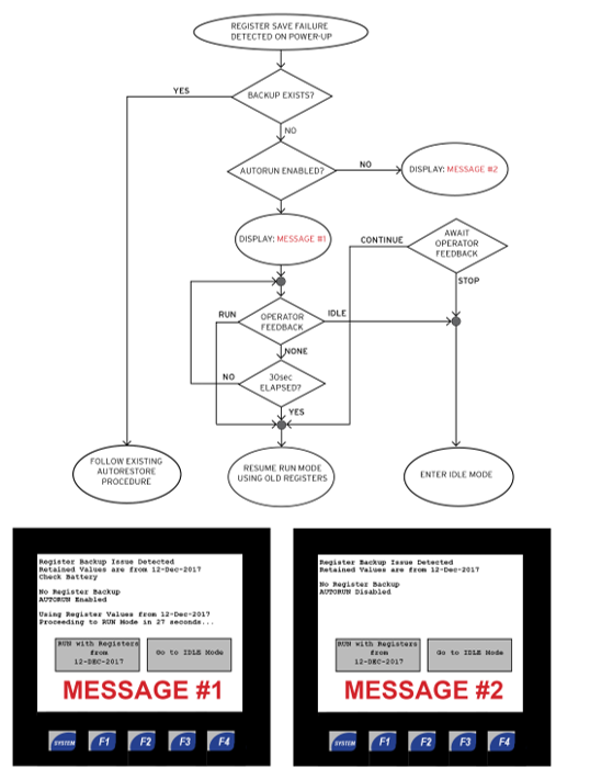
If the application is such that retaining register data is not important, if the unit just has to run, then it might be desirable to leave Pop-up Status messaging disabled. This will allow the unit to boot normally and go into RUN mode without operator intervention even if there were a problem saving register data at the last power-down.
If it is important to know at controller power-up that saving of register data had failed at the last power-down, then it might be desirable to enable Popup status on the OCS. The retention of Job setpoint data or PID tuning parameters are examples of why Popup status might be desired if a register save failure occurs. Popup Status messaging is enabled in the System Menu: Set Screen: Popup Status. How the Fail-Safe system is used or not used will dictate if operator intervention is required at power-up in the event of a register save failure.
-
If Pop-up status is enabled and Autorun is enabled in the Fail-Safe System, there is a delay to allow the operator time to stop the unit from going into RUN mode. After a 30 seconds timeout, the unit continues to boot and goes into RUN mode.
-
If Pop-up status is enabled and Autorun is disabled, operator intervention is required for the OCS controller to go into RUN mode.
-
If a Backup has been made in the Fail-Safe feature, and if a register save failure occurs at power-down, the OCS unit will load register data from the Backup when the unit boots up. Periodic Backups can be made from program logic by writing to %SR164.
-
See System Register Table for details about %SR164 .
If a register backup issue is detected and the warning screen is displayed the battery should be checked. The battery most likely needs to be recharged or possibly needs to be replaced.
See also Check Battery Procedure.
The following flowchart describes the operation when Popup Status is enabled.
Check Battery Procedure
The following procedure should be used to determine the battery condition.
-
Within the first two minutes after power up, while the unit is in state 11, Waiting (%SR196), check the battery voltage from the System Menu or %SR198.
-
When charging, the voltage reading is affected by the charging circuit and therefore will not be an accurate read. Check battery voltage in a non-charging state.
-
-
A battery may be considered low at less than 4.0 volts. But this is not an indication of a bad battery.
-
Any low battery should be given time to charge before deciding if it is bad or not.
-
In general, let the OCS charge the battery overnight or at least for a few hours, cycle power to the controller, and check the battery voltage during the Waiting state.
-
-
There are 5 charging states, which are based on battery temperature. (not ambient)
-
Not Charging = below 0°C
-
Cold Charging = 0-10°C - charge current = 20mA (Charges to 4.2 volts)
-
Normal Charging = 11-45°C - charge current = 100mA (Charges to 4.2 volts)
-
Hot Charging = 46-60°C - charge current = 20mA (Charges to 4.1V)
-
Not Charging = greater than 60°C
-
-
The battery temperature can be gauged by taking the CPU temperature and subtracting 30°C.
-
For example: In battery status, CPU temperature shows 73°C. The battery temperature is 43°C and the charging state would be state 1, Normal Charging.
-
-
When charging in state 2 (Hot Charging) or state 5 (Cold Charging) the current is lower and so will take much longer to charge. (See %SR196 for state in System Register Table).
-
States 2 or 5 can take up to 40 hours to fully charge a battery, depending on its level at the beginning of charging.
-
State 1, Normal Charging can take up to 8 hours to fully charge a battery, depending on its level at the beginning of charging.
-
If a battery is only slightly low or close to fully charged, it may only take a few minutes to fully charge the battery.
-
-
If a battery is completely dead, the battery status from System Menu or %SR198 will still show around 3.2 to 3.5 volts. This is not the battery, but the supporting circuitry voltage.
-
If the battery if very low or dead, the OCS will fail self-test and show a ‘Battery: Warning’ in diagnostics. %SR55.13 will be set ON.
-
3.2 to 3.5 volts is very low. In this case it would be a good idea to remove the battery and check it with a volt meter.
-
If the battery shows 1 volt or less, it is dead and should be replaced.
-
If the battery measures greater than 1 volt, let it charge for a few hours and see if there is improvement or not by checking the voltage while the OCS is in a non-charging state such as the first two minutes after powering up the unit.
-
-
Battery Replacement
Refer to the User Manual, MAN1029, for more details.
-
Make sure there is a backup of your register data. Using the Clone feature is an easy option (requires micro SD). You may also upload the program and registers using Cscape.
-
Remove power from the unit.
-
Follow directions in the user manual for replacing the battery.
-
Apply power and restore program and registers if necessary.
-
Allow the unit to remain powered near room temperature (10-35°C) for 6 to 8 hours. This will ensure the battery is fully charged properly for the first time.
-
Once the battery is charged, test the battery function by removing power and re-applying. Registers and clock function should be retained and there be no error messages on power up.
-
NOTE: On first power-up after replacing a battery, it is normal for the unit to fail the self-test and popup the Register Backup Issue Detected message. After the battery has been given time to charge, on subsequent power-ups the messages should go away, and the unit should pass self-tests.
-
Once charged, the battery management system will maintain the battery at optimal charge depending on use and temperature.